a

Breaking

Tuesday, December 21, 2021

6:29 AM

Mini Tesla coil Musical

Tesla coil adalah alat yang bisa menciptakan petir tegangan tinggi, saya sangat suka sekali dengan Tesla coil tapi saya suka Tesla coil versi mini karena menggunakan tegangan kecil sehingga meminimalkan resiko kesetrum atau mosfet meledak. Dan untuk yang sekarang yang akan kita buat adalah versi Tesla coil mini yang sering dijual di marketplace terutama yang berasal dari Cina seperti AliExpress dan lain-lain. 
Tesla coil ini sering tersedia dalam bentuk kit yang sudah siap untuk dimainkan atau ada juga versi yang belum disolder, namun kita bisa membuatnya sendiri dengan bahan-bahan yang lebih mudah didapatkan di toko sparepart elektronik. Tesla coil mini ini hanya menggunakan beberapa komponen saja tapi dengan hasil yang lumayan bagus dan juga versi yang ini sudah bisa memainkan musik dengan petir yang berfungsi sebagai speakernya. 
Berikut ini skemanya:
Dan ini penampakan layout pcbnya:


Untuk lilitan primer bisa menggunakan kabel dengan jumlah lilitan L1 yaitu1 lilitan sedangkan lilitan sekunder L2 saya menggunakan kawat tembaga ukuran 0, 12mm yang dililitkan pada pipa paralon diameter 1/2 inch dengan jumlah lilitan 350 lilitan. Sedangkan untuk suplai bisa menggunakan antara 15 sampai 24 volt.

Video:

Untuk file Gerber, skema dan pcb bisa di download di:

Monday, March 13, 2017

5:25 AM

Membuat Robot Obstacle Avoider Tanpa Servo

Robot Obstacle Avoider mungkin merupakan salah satu robot paling dasar setelah robot line follower. Bagi yang masih newbie seperti saya mungkin artikel ini dapat sedikit membantu, karena saya sendiri sudah berhasil mencobanya dan berhasil.

Salah satu hal yang jadi permasalahan dari pembuatan robot ini adalah harga rangka akrilik yang masih mahal, untuk mengakalinya mungkin kamu bisa membuatnya dengan bahan dan peralatan yang ada. Oke mari kita buat!!

Alat dan Bahan:


  • Arduino Uno

  • Adafruit Motor Driver L293D

  • Rangka/chasis akrilik

  • 2 buah geared motor + ban

  • Kotak baterai

  • Ban tengah yang dapat berputar (gak tau namanya :p)

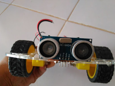
  • Sensor Ultrasonik

  • Saklar

  • Beberapa buah baut + spacer

  • 4 buah baterai AA

  • Kabel secukupnya


Merangkai Chasis:


  • Berhubung saya membeli rangka satu paket beserta dc motor dan lainnya, jadi tinggal mengikuti instruksi yang ada di panduannya, tapi untuk gambaran silahkan lihat foto2 dibawah!


Koneksi Kabel:


  •  Baterai → Saklar → EXT_PWR (Motor Driver Shield)

  • VCC Sensor Ultrasonik → 5v

  • GND Sensor Ultrasonik → GND

  • Trig Sensor Ultrasonik → Pin 12

  • Echo Sensor Ultrasonik → Pin 13

  • Motor 1 → M1  (Motor Driver Shield)

  • Motor 2  → M2 (Motor Driver Shield)


Untuk motor tidak perlu khawatir terbalik kabelnya, jika pada saat nanti dinyalakan ada salah satu motor ada yang bergerak mundur tinggal dibalik kabelnya. Karena seharusnya pada saat dinyalakan semua motor bergerak maju dengan patokan sensor ultrasonik lah yang berada didepan.

Source Code:


/* Code Written by Roy Pe'er. I've explained all the code in the grey comments.
I recommend you to go over the code, examine it, play with it, improve it and modify it according to your needs.
For more awesome videos, subsrice to my channel:
http://www.youtube.com/subscription_center?add_user=Roypeer1
*/


#include <AFMotor.h> //import your motor shield library
#define trigPin 12 // define the pins of your sensor
#define echoPin 13
AF_DCMotor motor1(1,MOTOR12_64KHZ); // set up motors.
AF_DCMotor motor2(2, MOTOR12_8KHZ);

void setup() {
Serial.begin(9600); // begin serial communitication
Serial.println("Motor test!");
pinMode(trigPin, OUTPUT);// set the trig pin to output (Send sound waves)
pinMode(echoPin, INPUT);// set the echo pin to input (recieve sound waves)
motor1.setSpeed(105); //set the speed of the motors, between 0-255
motor2.setSpeed (105);
}

void loop() {

long duration, distance; // start the scan
digitalWrite(trigPin, LOW);
delayMicroseconds(2); // delays are required for a succesful sensor operation.
digitalWrite(trigPin, HIGH);

delayMicroseconds(10); //this delay is required as well!
digitalWrite(trigPin, LOW);
duration = pulseIn(echoPin, HIGH);
distance = (duration/2) / 29.1;// convert the distance to centimeters.
if (distance < 25)/*if there's an obstacle 25 centimers, ahead, do the following: */ {
Serial.println ("Close Obstacle detected!" );
Serial.println ("Obstacle Details:");
Serial.print ("Distance From Robot is " );
Serial.print ( distance);
Serial.print ( " CM!");// print out the distance in centimeters.

Serial.println (" The obstacle is declared a threat due to close distance. ");
Serial.println (" Turning !");
motor1.run(FORWARD); // Turn as long as there's an obstacle ahead.
motor2.run (BACKWARD);

}
else {
Serial.println ("No obstacle detected. going forward");
delay (15);
motor1.run(FORWARD); //if there's no obstacle ahead, Go Forward!
motor2.run(FORWARD);
}


}

Foto:


Video:


Friday, March 10, 2017

11:56 PM

Membuat Polyphonic Piano Arduino (OctoSynth)

Kemarin ada teman yang meminta saya untuk mencari referensi tentang proyek yang akan dia buat, karena saya termasuk awam dalam arduino akhirnya mencari info di youtube dan akhirnya "tersesat" di sebuah video yang berisi tentang membuat polyphonic piano dengan arduino.

Rangkaian ini cukup sederhana tapi hasilnya lumayan bagus karena itu saya coba untuk membuatnya juga. Jika kamu ingin mencari referensi yang lebih lengkap tentang proyek ini silahkan cari di google dengan keyword "OctoSynth".

Alat dan Bahan:


Koneksi Kabel:


  • Pin D11 → Out ke speaker/amplifier

  • Pin D6 → Do

  • Pin D7 → Re

  • Pin A0 → Mi

  • Pin A1 → Fa

  • Pin A2 → So

  • Pin A3 → La

  • Pin A4 → Si

  • Pin A5 → Do*


Source Code:


// OCTOSynth-0.2 
//
// Joe Marshall 2011
// Resonant filter based on Meeblip (meeblip.noisepages.com)
// Interrupt setup code based on code by Martin Nawrath (http://interface.khm.de/index.php/lab/experiments/arduino-dds-sinewave-generator/)
// oscillators and inline assembler optimisation by me.
//
// key input is from 8 capacitive inputs on digital input 6,7, and analog inputs 0-6
// each input is a single wire, going to something metal to touch
// (I used a bunch of big carriage bolts)
//
// sensing of this is done by getNoteKeys, using the method described at:
// http://www.arduino.cc/playground/Code/CapacitiveSensor
//
// I use assembler with an unrolled loop using 16 registers to detect this
// this makes things much more accurate than the C loop described on the link above
// as we are measuring the relevant delay in single processor cycles.
// It seems to be happy even with battery power, detecting up to 8 concurrent
// touches.

// The waves are all defined at the very top, because we are forcing them to align to 256 byte boundaries
// doing this makes the oscillator code quicker (as calculating a wave offset is just
// a matter of replacing the low byte of the address).
// Having said that, other arduino stuff probably gets loaded in here first
// because the aligned attribute seems to add a couple of hundred bytes to the code

#define TEST_PATTERN_INTRO

//#define FILTER_LPF_NONE
#define FILTER_LPF_HACK


// table of 256 sine values / one sine period / stored in flash memory
char sine256[256] __attribute__ ((aligned(256))) = {
0 , 3 , 6 , 9 , 12 , 15 , 18 , 21 , 24 , 27 , 30 , 33 , 36 , 39 , 42 , 45 ,
48 , 51 , 54 , 57 , 59 , 62 , 65 , 67 , 70 , 73 , 75 , 78 , 80 , 82 , 85 , 87 ,
89 , 91 , 94 , 96 , 98 , 100 , 102 , 103 , 105 , 107 , 108 , 110 , 112 , 113 , 114 , 116 ,
117 , 118 , 119 , 120 , 121 , 122 , 123 , 123 , 124 , 125 , 125 , 126 , 126 , 126 , 126 , 126 ,
127 , 126 , 126 , 126 , 126 , 126 , 125 , 125 , 124 , 123 , 123 , 122 , 121 , 120 , 119 , 118 ,
117 , 116 , 114 , 113 , 112 , 110 , 108 , 107 , 105 , 103 , 102 , 100 , 98 , 96 , 94 , 91 ,
89 , 87 , 85 , 82 , 80 , 78 , 75 , 73 , 70 , 67 , 65 , 62 , 59 , 57 , 54 , 51 ,
48 , 45 , 42 , 39 , 36 , 33 , 30 , 27 , 24 , 21 , 18 , 15 , 12 , 9 , 6 , 3 ,
0 , -3 , -6 , -9 , -12 , -15 , -18 , -21 , -24 , -27 , -30 , -33 , -36 , -39 , -42 , -45 ,
-48 , -51 , -54 , -57 , -59 , -62 , -65 , -67 , -70 , -73 , -75 , -78 , -80 , -82 , -85 , -87 ,
-89 , -91 , -94 , -96 , -98 , -100 , -102 , -103 , -105 , -107 , -108 , -110 , -112 , -113 , -114 , -116 ,
-117 , -118 , -119 , -120 , -121 , -122 , -123 , -123 , -124 , -125 , -125 , -126 , -126 , -126 , -126 , -126 ,
-127 , -126 , -126 , -126 , -126 , -126 , -125 , -125 , -124 , -123 , -123 , -122 , -121 , -120 , -119 , -118 ,
-117 , -116 , -114 , -113 , -112 , -110 , -108 , -107 , -105 , -103 , -102 , -100 , -98 , -96 , -94 , -91 ,
-89 , -87 , -85 , -82 , -80 , -78 , -75 , -73 , -70 , -67 , -65 , -62 , -59 , -57 , -54 , -51 ,
-48 , -45 , -42 , -39 , -36 , -33 , -30 , -27 , -24 , -21 , -18 , -15 , -12 , -9 , -6 , -3
};

char square256[256] __attribute__ ((aligned(256))) = {
127 , 127 , 127 , 127 , 127 , 127 , 127 , 127 , 127 , 127 , 127 , 127 , 127 , 127 , 127 , 127 ,
127 , 127 , 127 , 127 , 127 , 127 , 127 , 127 , 127 , 127 , 127 , 127 , 127 , 127 , 127 , 127 ,
127 , 127 , 127 , 127 , 127 , 127 , 127 , 127 , 127 , 127 , 127 , 127 , 127 , 127 , 127 , 127 ,
127 , 127 , 127 , 127 , 127 , 127 , 127 , 127 , 127 , 127 , 127 , 127 , 127 , 127 , 127 , 127 ,
127 , 127 , 127 , 127 , 127 , 127 , 127 , 127 , 127 , 127 , 127 , 127 , 127 , 127 , 127 , 127 ,
127 , 127 , 127 , 127 , 127 , 127 , 127 , 127 , 127 , 127 , 127 , 127 , 127 , 127 , 127 , 127 ,
127 , 127 , 127 , 127 , 127 , 127 , 127 , 127 , 127 , 127 , 127 , 127 , 127 , 127 , 127 , 127 ,
127 , 127 , 127 , 127 , 127 , 127 , 127 , 127 , 127 , 127 , 127 , 127 , 127 , 127 , 127 , 127 ,
-127 , -127 , -127 , -127 , -127 , -127 , -127 , -127 , -127 , -127 , -127 , -127 , -127 , -127 , -127 , -127 ,
-127 , -127 , -127 , -127 , -127 , -127 , -127 , -127 , -127 , -127 , -127 , -127 , -127 , -127 , -127 , -127 ,
-127 , -127 , -127 , -127 , -127 , -127 , -127 , -127 , -127 , -127 , -127 , -127 , -127 , -127 , -127 , -127 ,
-127 , -127 , -127 , -127 , -127 , -127 , -127 , -127 , -127 , -127 , -127 , -127 , -127 , -127 , -127 , -127 ,
-127 , -127 , -127 , -127 , -127 , -127 , -127 , -127 , -127 , -127 , -127 , -127 , -127 , -127 , -127 , -127 ,
-127 , -127 , -127 , -127 , -127 , -127 , -127 , -127 , -127 , -127 , -127 , -127 , -127 , -127 , -127 , -127 ,
-127 , -127 , -127 , -127 , -127 , -127 , -127 , -127 , -127 , -127 , -127 , -127 , -127 , -127 , -127 , -127 ,
-127 , -127 , -127 , -127 , -127 , -127 , -127 , -127 , -127 , -127 , -127 , -127 , -127 , -127 , -127 , -127
};
char triangle256[256] __attribute__ ((aligned(256))) = {
-127 , -125 , -123 , -121 , -119 , -117 , -115 , -113 , -111 , -109 , -107 , -105 , -103 , -101 , -99 , -97 ,
-95 , -93 , -91 , -89 , -87 , -85 , -83 , -81 , -79 , -77 , -75 , -73 , -71 , -69 , -67 , -65 ,
-63 , -61 , -59 , -57 , -55 , -53 , -51 , -49 , -47 , -45 , -43 , -41 , -39 , -37 , -35 , -33 ,
-31 , -29 , -27 , -25 , -23 , -21 , -19 , -17 , -15 , -13 , -11 , -9 , -7 , -5 , -3 , -1 ,
1 , 3 , 5 , 7 , 9 , 11 , 13 , 15 , 17 , 19 , 21 , 23 , 25 , 27 , 29 , 31 ,
33 , 35 , 37 , 39 , 41 , 43 , 45 , 47 , 49 , 51 , 53 , 55 , 57 , 59 , 61 , 63 ,
65 , 67 , 69 , 71 , 73 , 75 , 77 , 79 , 81 , 83 , 85 , 87 , 89 , 91 , 93 , 95 ,
97 , 99 , 101 , 103 , 105 , 107 , 109 , 111 , 113 , 115 , 117 , 119 , 121 , 123 , 125 , 127 ,
129 , 127 , 125 , 123 , 121 , 119 , 117 , 115 , 113 , 111 , 109 , 107 , 105 , 103 , 101 , 99 ,
97 , 95 , 93 , 91 , 89 , 87 , 85 , 83 , 81 , 79 , 77 , 75 , 73 , 71 , 69 , 67 ,
65 , 63 , 61 , 59 , 57 , 55 , 53 , 51 , 49 , 47 , 45 , 43 , 41 , 39 , 37 , 35 ,
33 , 31 , 29 , 27 , 25 , 23 , 21 , 19 , 17 , 15 , 13 , 11 , 9 , 7 , 5 , 3 ,
1 , -1 , -3 , -5 , -7 , -9 , -11 , -13 , -15 , -17 , -19 , -21 , -23 , -25 , -27 , -29 ,
-31 , -33 , -35 , -37 , -39 , -41 , -43 , -45 , -47 , -49 , -51 , -53 , -55 , -57 , -59 , -61 ,
-63 , -65 , -67 , -69 , -71 , -73 , -75 , -77 , -79 , -81 , -83 , -85 , -87 , -89 , -91 , -93 ,
-95 , -97 , -99 , -101 , -103 , -105 , -107 , -109 , -111 , -113 , -115 , -117 , -119 , -121 , -123 , -125
};
char sawtooth256[256] __attribute__ ((aligned(256))) = {
-127 , -127 , -126 , -125 , -124 , -123 , -122 , -121 , -120 , -119 , -118 , -117 , -116 , -115 , -114 , -113 ,
-112 , -111 , -110 , -109 , -108 , -107 , -106 , -105 , -104 , -103 , -102 , -101 , -100 , -99 , -98 , -97 ,
-96 , -95 , -94 , -93 , -92 , -91 , -90 , -89 , -88 , -87 , -86 , -85 , -84 , -83 , -82 , -81 ,
-80 , -79 , -78 , -77 , -76 , -75 , -74 , -73 , -72 , -71 , -70 , -69 , -68 , -67 , -66 , -65 ,
-64 , -63 , -62 , -61 , -60 , -59 , -58 , -57 , -56 , -55 , -54 , -53 , -52 , -51 , -50 , -49 ,
-48 , -47 , -46 , -45 , -44 , -43 , -42 , -41 , -40 , -39 , -38 , -37 , -36 , -35 , -34 , -33 ,
-32 , -31 , -30 , -29 , -28 , -27 , -26 , -25 , -24 , -23 , -22 , -21 , -20 , -19 , -18 , -17 ,
-16 , -15 , -14 , -13 , -12 , -11 , -10 , -9 , -8 , -7 , -6 , -5 , -4 , -3 , -2 , -1 ,
0 , 1 , 2 , 3 , 4 , 5 , 6 , 7 , 8 , 9 , 10 , 11 , 12 , 13 , 14 , 15 ,
16 , 17 , 18 , 19 , 20 , 21 , 22 , 23 , 24 , 25 , 26 , 27 , 28 , 29 , 30 , 31 ,
32 , 33 , 34 , 35 , 36 , 37 , 38 , 39 , 40 , 41 , 42 , 43 , 44 , 45 , 46 , 47 ,
48 , 49 , 50 , 51 , 52 , 53 , 54 , 55 , 56 , 57 , 58 , 59 , 60 , 61 , 62 , 63 ,
64 , 65 , 66 , 67 , 68 , 69 , 70 , 71 , 72 , 73 , 74 , 75 , 76 , 77 , 78 , 79 ,
80 , 81 , 82 , 83 , 84 , 85 , 86 , 87 , 88 , 89 , 90 , 91 , 92 , 93 , 94 , 95 ,
96 , 97 , 98 , 99 , 100 , 101 , 102 , 103 , 104 , 105 , 106 , 107 , 108 , 109 , 110 , 111 ,
112 , 113 , 114 , 115 , 116 , 117 , 118 , 119 , 120 , 121 , 122 , 123 , 124 , 125 , 126 , 127
};


#include "avr/pgmspace.h"


// log table for 128 filter cutoffs
unsigned char logCutoffs[128] = {0x01,0x01,0x01,0x01,0x01,0x01,0x01,0x01,0x01,0x01,0x02,0x02,0x02,0x02,0x02,0x02,0x02,0x02,0x02,0x02,0x02,0x02,0x02,0x02,0x02,0x02,0x02,0x02,0x02,0x02,0x03,0x04,0x04,0x04,0x04,0x04,0x05,0x05,0x05,0x05,0x06,0x06,0x06,0x06,0x06,0x06,0x07,0x08,0x08,0x08,0x09,0x09,0x0A,0x0A,0x0A,0x0A,0x0B,0x0C,0x0C,0x0C,0x0C,0x0D,0x0E,0x0F,0x10,0x11,0x12,0x12,0x13,0x14,0x15,0x16,0x17,0x18,0x19,0x1A,0x1B,0x1C,0x1E,0x20,0x21,0x22,0x23,0x24,0x26,0x28,0x2A,0x2C,0x2E,0x30,0x32,0x34,0x36,0x38,0x3A,0x40,0x42,0x44,0x48,0x4C,0x4F,0x52,0x55,0x58,0x5D,0x61,0x65,0x68,0x6C,0x70,0x76,0x7E,0x85,0x8A,0x90,0x96,0x9D,0xA4,0xAB,0xB0,0xBA,0xC4,0xCE,0xD8,0xE0,0xE8,0xF4,0xFF};

volatile unsigned int WAIT_curTime;
#define WAIT_UNTIL_INTERRUPT() WAIT_curTime=loopSteps; while(WAIT_curTime==loopSteps){}


#define SERIAL_OUT 0

// attack,decay are in 1/64ths per 125th of a second - ie. 1 = 0->1 in half a second
const int DECAY=3;
const int ATTACK=4;


volatile char* curWave=square256;

#define cbi(sfr, bit) (_SFR_BYTE(sfr) &= ~_BV(bit))
#define sbi(sfr, bit) (_SFR_BYTE(sfr) |= _BV(bit))

// this is supposedly the audio clock frequency - as
// you can see, measured freq may vary a bit from supposed clock frequency
// I'm not quite sure why
// const double refclk=31372.549; // =16MHz / 510
// const double refclk=31376.6; // measured


// variables used inside interrupt service declared as voilatile
// these variables allow you to keep track of time - as delay / millis etc. are
// made inactive due to interrupts being disabled.
volatile unsigned char loopSteps=0; // once per sample
volatile unsigned int loopStepsHigh=0; // once per 256 samples

// information about the current state of a single oscillator
struct oscillatorPhase
{
unsigned int phaseStep;
char volume;
unsigned int phaseAccu;
};

// the oscillators (8 of them)
struct oscillatorPhase oscillators[8];

// tword_m=pow(2,32)*dfreq/refclk; // calulate DDS new tuning word
// to get hz -> tuning word do: (pow(2,16) * frequency) / 31376.6
const unsigned int NOTE_FREQS[25]={273,289,307,325,344,365,386,409,434,460,487,516,546,579,613,650,688,729,773,819,867,919,974,1032,1093};

// thresholds for the capacitive sensing buttons
int calibrationThresholds[8]={0,0,0,0,0,0,0,0};

inline int getNoteKeys(boolean calibrate=false)
{

char PORTD_PINS=0b11000000; // (pins 6-7 - avoid pins 0,1 as they are used for serial port comms)
char PORTC_PINS=0b111111; //(analog pins 0-5)

const int MAX_LOOPS=16;
char port_values[MAX_LOOPS*2];

WAIT_UNTIL_INTERRUPT();
asm volatile (
// port D reading loop:
// DDRD &= ~(PORTD_PINS = 0x3f); // set pins 8-12 to input mode
"in %[temp],0x0a" "\n\t"
"andi %[temp],0x3f" "\n\t"
"out 0x0a,%[temp]" "\n\t"
// PORTD |= (PORTD_PINS); // set pins 8-12 pullup on
"in %[temp],0x0b" "\n\t"
"ori %[temp],0xC0" "\n\t"
"out 0x0b,%[temp]" "\n\t"
"in %0,0x09" "\n\t"
"in %1,0x09" "\n\t"
"in %2,0x09" "\n\t"
"in %3,0x09" "\n\t"
"in %4,0x09" "\n\t"
"in %5,0x09" "\n\t"
"in %6,0x09" "\n\t"
"in %7,0x09" "\n\t"
"in %8,0x09" "\n\t"
"in %9,0x09" "\n\t"
"in %10,0x09" "\n\t"
"in %11,0x09" "\n\t"
"in %12,0x09" "\n\t"
"in %13,0x09" "\n\t"
"in %14,0x09" "\n\t"
"in %15,0x09" "\n\t"
:
// outputs
"=r" (port_values[0]),
"=r" (port_values[2]),
"=r" (port_values[4]),
"=r" (port_values[6]),
"=r" (port_values[8]),
"=r" (port_values[10]),
"=r" (port_values[12]),
"=r" (port_values[14]),
"=r" (port_values[16]),
"=r" (port_values[18]),
"=r" (port_values[20]),
"=r" (port_values[22]),
"=r" (port_values[24]),
"=r" (port_values[26]),
"=r" (port_values[28]),
"=r" (port_values[30])
:[temp] "d" (0));

WAIT_UNTIL_INTERRUPT();
asm volatile (
// port C reading loop:
// DDRC &= ~(PORTC_PINS = 0xc0); // set pins 5-7 to input mode
"in %[temp],0x07" "\n\t"
"andi %[temp],0xc0" "\n\t"
"out 0x07,%[temp]" "\n\t"
// PORTC |= (PORTC_PINS); // set pins 5-7 pullup on
"in %[temp],0x08" "\n\t"
"ori %[temp],0x3F" "\n\t"
"out 0x08,%[temp]" "\n\t"
"in %0,0x06" "\n\t"
"in %1,0x06" "\n\t"
"in %2,0x06" "\n\t"
"in %3,0x06" "\n\t"
"in %4,0x06" "\n\t"
"in %5,0x06" "\n\t"
"in %6,0x06" "\n\t"
"in %7,0x06" "\n\t"
"in %8,0x06" "\n\t"
"in %9,0x06" "\n\t"
"in %10,0x06" "\n\t"
"in %11,0x06" "\n\t"
"in %12,0x06" "\n\t"
"in %13,0x06" "\n\t"
"in %14,0x06" "\n\t"
"in %15,0x06" "\n\t"
:
// outputs
"=r" (port_values[1]),
"=r" (port_values[3]),
"=r" (port_values[5]),
"=r" (port_values[7]),
"=r" (port_values[9]),
"=r" (port_values[11]),
"=r" (port_values[13]),
"=r" (port_values[15]),
"=r" (port_values[17]),
"=r" (port_values[19]),
"=r" (port_values[21]),
"=r" (port_values[23]),
"=r" (port_values[25]),
"=r" (port_values[27]),
"=r" (port_values[29]),
"=r" (port_values[31])
:[temp] "d" (0));

PORTC &= ~(PORTC_PINS); // pullup off pins 8-12
PORTD &= ~(PORTD_PINS); // pullup off pins 5-7
DDRC |= (PORTC_PINS); // discharge
DDRD |= (PORTD_PINS); // discharge

if(calibrate)
{
for(int c=0;c<8;c++)
{
for(int d=0;d<MAX_LOOPS;d++)
{
int liveNotes=((int*)port_values)[d];
liveNotes&=0x3fc0;
liveNotes>>=6;
if(liveNotes&(1<<c))
{
if(calibrationThresholds[c]<=d)
{
calibrationThresholds[c]=d+1;
}
break;
}
}
}
}
int liveNotes=0;
for(int c=0;c<8;c++)
{
int val = ((int*)port_values)[calibrationThresholds[c]+1];
val&=0x3fc0;
val>>=6;
if((val&(1<<c))==0)
{
liveNotes|=(1<<c);
}
}
return liveNotes;
}

// get capacitive touch on input 4 and output 3
// used for filter modulator
inline int getfiltermodulationtime()
{
static int running_average=0;
static int running_min=1024;
static int running_min_inc_count=0;
static boolean initialise_running_min=true;

unsigned int delayTime=0;
char PINNUM_OUT=3;
char PINNUM_IN=4;
char PIN_OUT=1<<PINNUM_OUT;
char PIN_IN=1<<PINNUM_IN;
// make sure inputs / outputs are set right
DDRD|=PIN_OUT;
DDRD&=~(PIN_IN);
WAIT_UNTIL_INTERRUPT();
PORTD|=PIN_OUT;
asm volatile (
"loopstart%=:" "\n\t"
"sbic 0x09,%[PINNUM_IN]" "\n\t"
"rjmp outloop%=" "\n\t"
"adiw %[delayTime],0x01" "\n\t"
"cpi %B[delayTime],0x02" "\n\t"
"brne loopstart%=" "\n\t"
"outloop%=:" "\n\t"
:[delayTime] "+&w" (delayTime)
:[PINNUM_IN] "I" (PINNUM_IN));
// set pin down - maybe don't bother timing, if it doesn't seem to add
// much accuracy?
WAIT_UNTIL_INTERRUPT();
PORTD&=~PIN_OUT;
asm(
"loopstart%=:" "\n\t"
"sbis 0x09,%[PINNUM_IN]" "\n\t"
"rjmp outloop%=" "\n\t"
"adiw %[delayTime],0x01" "\n\t"
"cpi %B[delayTime],0x02" "\n\t"
"brne loopstart%=" "\n\t"
"outloop%=:" "\n\t"
:[delayTime] "+&w" (delayTime)
:[PINNUM_IN] "I" (PINNUM_IN));
running_average=(running_average-(running_average>>4))+(delayTime>>4);
running_min_inc_count++;
if(running_min_inc_count==255)
{
if(initialise_running_min)
{
running_min=running_average;
running_min_inc_count=0;
initialise_running_min=false;
}else{
running_min_inc_count=0;
running_min++;
}
}
if(running_average<running_min)
{
running_min=running_average;
}
int touchVal=running_average-running_min;
if(touchVal>15)
{
touchVal-=15;
if(touchVal>99)
{
touchVal=99;
}
}else{
touchVal=0;
}
return touchVal;
}


// get capacitive touch on input 5 and output 3
// used for pitch bend
inline int getpitchbendtime()
{
static int running_average=0;
static int running_min=1024;
static int running_min_inc_count=0;
static boolean initialise_running_min=true;

unsigned int delayTime=0;
char PINNUM_OUT=3;
char PINNUM_IN=5;
char PIN_OUT=1<<PINNUM_OUT;
char PIN_IN=1<<PINNUM_IN;
// make sure inputs / outputs are set right
DDRD|=PIN_OUT;
DDRD&=~(PIN_IN);
WAIT_UNTIL_INTERRUPT();
PORTD|=PIN_OUT;
asm volatile (
"loopstart%=:" "\n\t"
"sbic 0x09,%[PINNUM_IN]" "\n\t"
"rjmp outloop%=" "\n\t"
"adiw %[delayTime],0x01" "\n\t"
"cpi %B[delayTime],0x02" "\n\t"
"brne loopstart%=" "\n\t"
"outloop%=:" "\n\t"
:[delayTime] "+&w" (delayTime)
:[PINNUM_IN] "I" (PINNUM_IN));
// set pin down - maybe don't bother timing, if it doesn't seem to add
// much accuracy?
WAIT_UNTIL_INTERRUPT();
PORTD&=~PIN_OUT;
asm(
"loopstart%=:" "\n\t"
"sbis 0x09,%[PINNUM_IN]" "\n\t"
"rjmp outloop%=" "\n\t"
"adiw %[delayTime],0x01" "\n\t"
"cpi %B[delayTime],0x02" "\n\t"
"brne loopstart%=" "\n\t"
"outloop%=:" "\n\t"
:[delayTime] "+&w" (delayTime)
:[PINNUM_IN] "I" (PINNUM_IN));
running_average=(running_average-(running_average>>4))+(delayTime>>4);
running_min_inc_count++;
if(running_min_inc_count==255)
{
if(initialise_running_min)
{
running_min=running_average;
running_min_inc_count=0;
initialise_running_min=false;
}else{
running_min_inc_count=0;
running_min++;
}
}
if(running_average<running_min)
{
running_min=running_average;
}
int touchVal=running_average-running_min;
if(touchVal>15)
{
touchVal-=15;
if(touchVal>99)
{
touchVal=99;
}
}else{
touchVal=0;
}
return touchVal;
}

unsigned int pitchBendTable[201]={241, 241, 241, 242, 242, 242, 242, 242, 242, 242, 243, 243, 243, 243, 243, 243, 243, 244, 244, 244, 244, 244, 244, 244, 245, 245, 245, 245, 245, 245, 245, 246, 246, 246, 246, 246, 246, 246, 247, 247, 247, 247, 247, 247, 247, 248, 248, 248, 248, 248, 248, 248, 249, 249, 249, 249, 249, 249, 249, 250, 250, 250, 250, 250, 250, 250, 251, 251, 251, 251, 251, 251, 251, 252, 252, 252, 252, 252, 252, 253, 253, 253, 253, 253, 253, 253, 254, 254, 254, 254, 254, 254, 254, 255, 255, 255, 255, 255, 255, 256,
256,256, 256, 256, 256, 256, 256, 256, 257, 257, 257, 257, 257, 257, 257, 258, 258, 258, 258, 258, 258, 259, 259, 259, 259, 259, 259, 259, 260, 260, 260, 260, 260, 260, 260, 261, 261, 261, 261, 261, 261, 262, 262, 262, 262, 262, 262, 262, 263, 263, 263, 263, 263, 263, 264, 264, 264, 264, 264, 264, 264, 265, 265, 265, 265, 265, 265, 266, 266, 266, 266, 266, 266, 266, 267, 267, 267, 267, 267, 267, 268, 268, 268, 268, 268, 268, 269, 269, 269, 269, 269, 269, 269, 270, 270, 270, 270, 270, 270, 271, 271};

void setupNoteFrequencies(int baseNote,int pitchBendVal /*-100 -> 100*/)
{
oscillators[0].phaseStep=NOTE_FREQS[baseNote];
oscillators[1].phaseStep=NOTE_FREQS[baseNote+2];
oscillators[2].phaseStep=NOTE_FREQS[baseNote+4];
oscillators[3].phaseStep=NOTE_FREQS[baseNote+5];
oscillators[4].phaseStep=NOTE_FREQS[baseNote+7];
oscillators[5].phaseStep=NOTE_FREQS[baseNote+9];
oscillators[6].phaseStep=NOTE_FREQS[baseNote+11];
oscillators[7].phaseStep=NOTE_FREQS[baseNote+12];

if(pitchBendVal<-99)
{
pitchBendVal=-99;
}else if(pitchBendVal>99)
{
pitchBendVal=99;
}
// Serial.print("*");
// Serial.print(pitchBendVal);
unsigned int pitchBendMultiplier=pitchBendTable[pitchBendVal+100];
// Serial.print(":");
// Serial.print(pitchBendMultiplier);
for(int c=0;c<8;c++)
{
// multiply 2 16 bit numbers together and shift 8 without precision loss
// requires assembler really
volatile unsigned char zeroReg=0;
volatile unsigned int multipliedCounter=oscillators[c].phaseStep;
asm volatile
(
// high bytes mult together = high byte
"ldi %A[outVal],0" "\n\t"
"mul %B[phaseStep],%B[pitchBend]" "\n\t"
"mov %B[outVal],r0" "\n\t"
// ignore overflow into r1 (should never overflow)
// low byte * high byte -> both bytes
"mul %A[phaseStep],%B[pitchBend]" "\n\t"
"add %A[outVal],r0" "\n\t"
// carry into high byte
"adc %B[outVal],r1" "\n\t"
// high byte* low byte -> both bytes
"mul %B[phaseStep],%A[pitchBend]" "\n\t"
"add %A[outVal],r0" "\n\t"
// carry into high byte
"adc %B[outVal],r1" "\n\t"
// low byte * low byte -> round
"mul %A[phaseStep],%A[pitchBend]" "\n\t"
// the adc below is to round up based on high bit of low*low:
"adc %A[outVal],r1" "\n\t"
"adc %B[outVal],%[ZERO]" "\n\t"
"clr r1" "\n\t"
:[outVal] "=&d" (multipliedCounter)
:[phaseStep] "d" (oscillators[c].phaseStep),[pitchBend] "d"( pitchBendMultiplier),[ZERO] "d" (zeroReg)
:"r1","r0"
);
oscillators[c].phaseStep=multipliedCounter;
}
// Serial.print(":");
// Serial.print(NOTE_FREQS[baseNote]);
// Serial.print(":");
// Serial.println(oscillators[0].phaseStep);

}

void setup()
{
Serial.begin(9600); // connect to the serial port
#ifndef FILTER_LPF_NONE
setFilter(127, 0);
#endif

pinMode(11, OUTPUT); // pin11= PWM output / frequency output

setupNoteFrequencies(12,0);

for(int c=0;c<8;c++)
{
oscillators[c].volume=0;
}

Setup_timer2();

// disable interrupts to avoid timing distortion
cbi (TIMSK0,TOIE0); // disable Timer0 !!! delay() is now not available
sbi (TIMSK2,TOIE2); // enable Timer2 Interrupt


// calibrate the unpressed key values

for(int x=0;x<1024;x++)
{
getNoteKeys(true);
int steps=loopSteps;
WAIT_UNTIL_INTERRUPT();
// int afterSteps=loopSteps;
// Serial.println(afterSteps-steps);
}
// test pattern intro
#ifdef TEST_PATTERN_INTRO
int filtValue=255;
byte notes[]={0x1,0x4,0x10,0x80,0x80,0x80,0x1,0x2,0x4,0x8,0x10,0x20,0x40,0x80,0x40,0x20,0x10,0x8,0x4,0x2,0x1,0x1,0x1,0x00,0x00,0x1,0x1,0x1,0x1,0x00,0x00,0x5,0x5,0x5,0x5,0x00,0x00,0x15,0x15,0x15,0x15,0x15,0x00,0x00,0x95,0x95,0x95,0x95,0x95,0x95,0x00};
for(int note=0;note<sizeof(notes)/sizeof(byte);note++)
{

int noteCount=0;
for(int c=0;c<8;c++)
{
if(notes[note]&(1<<c))
{
noteCount+=1;
}
}
for(int c=0;c<8;c++)
{
if(notes[note]&(1<<c))
{
oscillators[c].volume=63/noteCount;
}else
{
oscillators[c].volume=0;
}
}
for(int c=0;c<50;c++)
{
// might as well keep calibrating here
// nb: each calibration loop = at least 1 interrupt

getNoteKeys(true);
#ifndef FILTER_LPF_NONE
setFilter(127-c, 64);
#endif

}
}
#else
// just beep to show calibration is done
oscillators[0].volume=63;
for(int c=0;c<20;c++)
{
WAIT_UNTIL_INTERRUPT();
}
oscillators[0].volume=63;

#endif
Serial.println("Calibrations:");
for(int c=0;c<8;c++)
{
Serial.print(c);
Serial.print(":");
Serial.println(calibrationThresholds[c]);
}

}


void loop()
{
// we keep a list of 'raw' volumes - and turn down the volume if a chord is taking >64 volume total
// this is to allow chording without reducing the volume of single notes
int rawVolumes[8]={0,0,0,0,0,0,0,0};
int curNote=0;
unsigned int filterSweep=64;
const int MIN_SWEEP=64;
const int MAX_SWEEP=127;
const int SWEEP_SPEED=3;
int sweepDir=SWEEP_SPEED;
unsigned int lastStep=loopStepsHigh;
unsigned curStep=loopStepsHigh;
while(1)
{
lastStep=curStep;
curStep=loopStepsHigh;
// NOTE: timers do not work in this code (interrupts disabled / speeds changed), so don't even think about calling: delay(), millis / micros etc.
// each loopstep is roughly 31250 / second
// this main loop will get called once every 3 or 4 samples if the serial output is turned off, maybe slower otherwise

int liveNotes=getNoteKeys();
// we are right after an interrupt (as loopStep has just been incremented)
// so we should have enough time to do the capacitative key checks

if(lastStep!=curStep)
{
int totalVolume=0;
for(int c=0;c<8;c++)
{
if((liveNotes&(1<<c))==0)
{
rawVolumes[c]-=DECAY*(curStep-lastStep);
if(rawVolumes[c]<0)rawVolumes[c]=0;
if(SERIAL_OUT)Serial.print(".");
}
else
{
rawVolumes[c]+=ATTACK*(curStep-lastStep);
if(rawVolumes[c]>63)rawVolumes[c]=63;
if(SERIAL_OUT)Serial.print(c);
}
totalVolume+=rawVolumes[c];
}
WAIT_UNTIL_INTERRUPT();
if( totalVolume<64 )
{
for(int c=0;c<8;c++)
{
oscillators[c].volume=rawVolumes[c];
}
}else
{
// total volume too much, scale down to avoid clipping
for(int c=0;c<8;c++)
{
oscillators[c].volume=(rawVolumes[c]*63)/totalVolume;
}
}
}
if(SERIAL_OUT)Serial.println("");
#ifndef FILTER_LPF_NONE
/* if(liveNotes==0)
{
filterSweep=64;
sweepDir=SWEEP_SPEED;
}
filterSweep+=sweepDir;
if(filterSweep>=MAX_SWEEP)
{
filterSweep=MAX_SWEEP;
sweepDir=-sweepDir;
}
else if (filterSweep<=MIN_SWEEP)
{
sweepDir=-sweepDir;
filterSweep=MIN_SWEEP;
}*/
// Serial.println((int)filterValue);
// filterSweep=127-(getpitchbendtime()>>1);
WAIT_UNTIL_INTERRUPT();
setFilter(150-(getfiltermodulationtime()),220);
#endif
WAIT_UNTIL_INTERRUPT();
setupNoteFrequencies(12,-getpitchbendtime());

// we are right after an interrupt again (as loopStep has just been incremented)
// so we should have enough time to check the pitch bend capacitance without going over another sample, timing is quite important here
// need to balance using a big enough resistor to get decent sensing distance with taking too long to sample
// check the pitch bend input

}
}
//******************************************************************
// timer2 setup
// set prscaler to 1, PWM mode to phase correct PWM, 16000000/510 = 31372.55 Hz clock
void Setup_timer2() {

// Timer2 Clock Prescaler to : 1
sbi (TCCR2B, CS20);
cbi (TCCR2B, CS21);
cbi (TCCR2B, CS22);

// Timer2 PWM Mode set to Phase Correct PWM
cbi (TCCR2A, COM2A0); // clear Compare Match
sbi (TCCR2A, COM2A1);

sbi (TCCR2A, WGM20); // Mode 1 / Phase Correct PWM
cbi (TCCR2A, WGM21);
cbi (TCCR2B, WGM22);
}

#ifdef FILTER_LPF_BIQUAD
char filtValueA1=0,filtValueA2=0,filtValueA3=0,filtValueB1=0,filtValueB2=0;
volatile unsigned char filtCoeffA1=255;
volatile char filtCoeffB1=127;
volatile unsigned char filtCoeffB2=255;
#endif
#ifdef FILTER_LPF_HACK
// hacked low pass filter - 2 pole resonant -
// a += f*((in-a)+ q*(a-b)
// b+= f* (a-b)
int filterA=0;
int filterB=0;
unsigned char filterQ=0;
unsigned char filterF=255;

inline void setFilterRaw(unsigned char filterF, unsigned char resonance)
{
unsigned char tempReg=0,tempReg2=0;
asm volatile("ldi %[tempReg], 0xff" "\n\t"
"sub %[tempReg],%[filtF] " "\n\t"
"lsr %[tempReg]" "\n\t"
"ldi %[tempReg2],0x04" "\n\t"
"add %[tempReg],%[tempReg2]" "\n\t"
"sub %[reso],%[tempReg]" "\n\t"
"brcc Res_Overflow%=" "\n\t"
"ldi %[reso],0x00" "\n\t"
"Res_Overflow%=:" "\n\t"
"mov %[filtQ],%[reso]" "\n\t"
:[tempReg] "=&d" (tempReg),[tempReg2] "=&d" (tempReg2),[filtQ] "=&d" (filterQ): [reso] "d" (resonance), [filtF] "d" (filterF) );
}

inline void setFilter(unsigned char f, unsigned char resonance)
{
if(f>127)f=127;
filterF=logCutoffs[f];
setFilterRaw(filterF,resonance);
}
#endif


#define HIBYTE(__x) ((char)(((unsigned int)__x)>>8))
#define LOBYTE(__x) ((char)(((unsigned int)__x)&0xff))

// oscillator main loop (increment wavetable pointer, and add it to the output registers)
// 13 instructions - should take 14 processor cycles according to the datasheet
// in theory I think this means that each oscillator should take 1.5% of cpu
// (plus a constant overhead for interrupt calls etc.)
// Note: this used to do all the stepvolume loads near the start, but they are now interleaved in the
// code, this is because ldd (load with offset) takes 2 instructions,
// versus ld,+1 (load with post increment) and st,+1 which are 1 instruction - we can do this because:
//
// a)the step (which doesn't need to be stored back) is in memory before the
// phase accumulator (which does need to be stored back once the step is added
//
// b)the phase assumulator is stored in low byte, high byte order, meaning that we
// can add the first bytes together, then store that byte incrementing the pointer,
// then load the high byte, add the high bytes together and store incrementing the pointer
//
// I think this is the minimum number of operations possible to code this oscillator in, because
// 1)There are 6 load operations required (to load stepHigh/Low,phaseH/L,volume, and the value from the wave)
// 2)There are 2 add operations required to add to the phase accumulator
// 3)There are 2 store operations required to save the phase accumulator
// 4)There is 1 multiply (2 instruction cycles) required to do the volume
// 5)There are 2 add operations required to add to the final output
//
// 6+2+2+2+2 = 14 instruction cycles

#define OSCILLATOR_ASM \
/* load phase step and volume*/ \
"ld %A[tempStep],%a[stepVolume]+" "\n\t" \
"ld %B[tempStep],%a[stepVolume]+" "\n\t" \
"ld %[tempVolume],%a[stepVolume]+" "\n\t" \
/* load phase accumulator - high byte goes straight*/ \
/* into the wave lookup array (wave is on 256 byte boundary*/ \
/* so we can do this without any adds */ \
/* Do the phase adds in between the two loads, as load with offset is slower than
just a normal load
*/\
"ld %A[tempPhaseLow],%a[stepVolume]" "\n\t" \
/* add phase step low */ \
"add %[tempPhaseLow],%A[tempStep]" "\n\t"\
/* store phase accumulator low */ \
"st %a[stepVolume]+,%[tempPhaseLow]" "\n\t" \
/* load phase accumulator high*/\
"ld %A[waveBase],%a[stepVolume]" "\n\t" \
/* add phase step high - with carry from the add above */\
"adc %A[waveBase],%B[tempStep]" "\n\t"\
/* store phase step high */\
"st %a[stepVolume]+,%A[waveBase]" "\n\t" \
/* now lookup from the wave - high byte = wave pointer, low byte=offset*/ \
"ld %[tempPhaseLow],%a[waveBase]" "\n\t" \
/* now multiply by volume*/ \
"muls %[tempPhaseLow],%[tempVolume]" "\n\t" \
/* r0 now contains a sample - add it to output value*/ \
"add %A[outValue],r0" "\n\t" \
"adc %B[outValue],r1" "\n\t" \
/* go to next oscillator - stepVolume is pointing at next*/ \
/* oscillator already */ \


//******************************************************************
// Timer2 Interrupt Service at 31372,550 KHz = 32uSec
// this is the timebase REFCLOCK for the DDS generator
// FOUT = (M (REFCLK)) / (2 exp 32)
// runtime : ?
ISR(TIMER2_OVF_vect) {


// now set up the next value
// this loop takes roughly 172 cycles (214 including the push/pops) - we have 510, so roughly 50% of the processor going spare for non-audio tasks
// the low pass filter also takes some cycles

int outValue;

// pointers:
// X = oscillator phase accumulator
// Y = oscillator step and volume
// Z = wave pos - needs to add to base
int tempStep=0;
char tempPhaseLow=0,tempVolume=0;
int tempWaveBase=0;
asm volatile (
"ldi %A[outValue],0" "\n\t"
"ldi %B[outValue],0" "\n\t"
// oscillator 0
// uncomment the code below to check
// that registers aren't getting double assigned
/* "lds %A[outValue],0x00" "\n\t"
"lds %B[outValue],0x01" "\n\t"
"lds %A[tempPhaseLow],0x02" "\n\t"
// "lds %B[tempPhase],0x03" "\n\t"
"lds %A[tempStep],0x04" "\n\t"
"lds %B[tempStep],0x05" "\n\t"
"lds %[tempVolume],0x06" "\n\t"
"lds %[ZERO],0x07" "\n\t"
"lds %A[tempWaveBase],0x08" "\n\t"
"lds %B[tempWaveBase],0x09" "\n\t"
"lds %A[phaseAccu],0x0a" "\n\t"
"lds %B[phaseAccu],0x0b" "\n\t"
"lds %A[stepVolume],0x0c" "\n\t"
"lds %B[stepVolume],0x0d" "\n\t"
"lds %A[waveBase],0x0e" "\n\t"
"lds %B[waveBase],0x0f" "\n\t"*/
OSCILLATOR_ASM
OSCILLATOR_ASM
OSCILLATOR_ASM
OSCILLATOR_ASM
OSCILLATOR_ASM
OSCILLATOR_ASM
OSCILLATOR_ASM
OSCILLATOR_ASM
:
// outputs
[tempPhaseLow] "=&d" (tempPhaseLow),
[tempStep] "=&d" (tempStep),
[tempVolume] "=&d" (tempVolume),
[outValue] "=&d" (outValue)
:
// inputs
[stepVolume] "y" (&oscillators[0].phaseStep),
[waveBase] "z" (256*(((unsigned int)curWave)>>8))
:
// other registers we clobber (by doing multiplications)
"r1"
);

// at this point outValue = oscillator value
// it is currently maxed to full volume / 4
// to allow some headroom for filtering


#ifdef FILTER_LPF_HACK

// a low pass filter based on the one from MeeBlip (http://meeblip.noisepages.com)
// a += f*((in-a)+ q*(a-b)
// b+= f* (a-b)
// outValue>>=3;
// started at 4700
// 4686
int tempReg,tempReg2=0;
unsigned char zeroRegFilt=0;
// de-volatilisati
unsigned char filtF=filterF;
unsigned char filtQ=filterQ;
asm volatile(
"sub %A[outVal],%A[filtA]" "\n\t"
"sbc %B[outVal],%B[filtA]" "\n\t"
"brvc No_overflow1%=" "\n\t"
"ldi %A[outVal],0b00000001" "\n\t"
"ldi %B[outVal],0b10000000" "\n\t"
"No_overflow1%=:" "\n\t"
// outVal = (in - filtA)
"mov %A[tempReg],%A[filtA]" "\n\t"
"mov %B[tempReg],%B[filtA]" "\n\t"
"sub %A[tempReg],%A[filtB]" "\n\t"
"sbc %B[tempReg],%B[filtB]" "\n\t"
"brvc No_overflow3%=" "\n\t"
"ldi %A[tempReg],0b00000001" "\n\t"
"ldi %B[tempReg],0b10000000" "\n\t"
"No_overflow3%=:" "\n\t"
// tempReg = (a-b)
"mulsu %B[tempReg],%[filtQ]" "\n\t"
"movw %A[tempReg2],r0" "\n\t"
// tempReg2 = (HIBYTE(a-b))*Q
"mul %A[tempReg],%[filtQ]" "\n\t"
"add %A[tempReg2],r1" "\n\t"
"adc %B[tempReg2],%[ZERO]" "\n\t"
"rol r0" "\n\t"
"brcc No_Round1%=" "\n\t"
"inc %A[tempReg2]" "\n\t"
"No_Round1%=:" "\n\t"
// at this point tempReg2 = (a-b)*Q (shifted appropriately and rounded)
// "clc" "\n\t"
"lsl %A[tempReg2]" "\n\t"
"rol %B[tempReg2]" "\n\t"
// "clc" "\n\t"
"lsl %A[tempReg2]" "\n\t"
"rol %B[tempReg2]" "\n\t"
// tempReg2 = (a-b)*Q*4
"add %A[outVal],%A[tempReg2]" "\n\t"
"adc %B[outVal],%B[tempReg2]" "\n\t"
"brvc No_overflow4%=" "\n\t"
"ldi %A[outVal],0b11111111" "\n\t"
"ldi %B[outVal],0b01111111" "\n\t"
"No_overflow4%=:" "\n\t"
// outVal = ((in-a) + (a-b)*(Q>>8)*4) - clipped etc
"mulsu %B[outVal],%[filtF]" "\n\t"
"movw %A[tempReg],r0" "\n\t"
"mul %A[outVal],%[filtF]" "\n\t"
"add %A[tempReg],r1" "\n\t"
"adc %B[tempReg],%[ZERO]" "\n\t"
"rol r0" "\n\t"
"brcc No_Round2%=" "\n\t"
"inc %A[tempReg]" "\n\t"
// tempReg = f* ((in-a) + (a-b)*(Q>>8)*4)
"No_Round2%=:" "\n\t"
"add %A[filtA],%A[tempReg]" "\n\t"
"adc %B[filtA],%B[tempReg]" "\n\t"
// A= A+ f* ((in-a) + (a-b)*(Q>>8)*4)
"brvc No_overflow5%=" "\n\t"
"ldi %A[outVal],0b11111111" "\n\t"
"ldi %B[outVal],0b01111111" "\n\t"
"No_overflow5%=:" "\n\t"
// now calculate B= f* (a - b)

"mov %A[tempReg],%A[filtA]" "\n\t"
"mov %B[tempReg],%B[filtA]" "\n\t"
"sub %A[tempReg],%A[filtB]" "\n\t"
"sbc %B[tempReg],%B[filtB]" "\n\t"
"brvc No_overflow6%=" "\n\t"
"ldi %A[tempReg],0b00000001" "\n\t"
"ldi %B[tempReg],0b10000000" "\n\t"
"No_overflow6%=:" "\n\t"
// tempReg = (a-b)
"mulsu %B[tempReg],%[filtF]" "\n\t"
"movw %A[tempReg2],r0" "\n\t"
"mul %A[tempReg],%[filtF]" "\n\t"
"add %A[tempReg2],r1" "\n\t"
"adc %B[tempReg2],%[ZERO]" "\n\t"
// tempReg2 = f*(a-b)
"add %A[filtB],%A[tempReg2]" "\n\t"
"adc %B[filtB],%B[tempReg2]" "\n\t"
"brvc No_overflow7%=" "\n\t"
"ldi %A[filtB],0b11111111" "\n\t"
"ldi %B[filtB],0b01111111" "\n\t"
"No_overflow7%=:" "\n\t"
// now b= b+f*(a-b)
"mov %A[outVal],%A[filtB]" "\n\t"
"mov %B[outVal],%B[filtB]" "\n\t"

// multiply outval by 4 and clip
"add %A[outVal],%A[filtB]" "\n\t"
"adc %B[outVal],%B[filtB]" "\n\t"
"brbs 3, Overflow_End%=" "\n\t"

"add %A[outVal],%A[filtB]" "\n\t"
"adc %B[outVal],%B[filtB]" "\n\t"
"brbs 3, Overflow_End%=" "\n\t"

"add %A[outVal],%A[filtB]" "\n\t"
"adc %B[outVal],%B[filtB]" "\n\t"
"brbs 3, Overflow_End%=" "\n\t"
"rjmp No_overflow%=" "\n\t"
"Overflow_End%=:" "\n\t"
"brbs 2,Overflow_High%=" "\n\t"
"ldi %A[outVal],0b00000001" "\n\t"
"ldi %B[outVal],0b10000000" "\n\t"
"rjmp No_overflow%=" "\n\t"
"Overflow_High%=:" "\n\t"
"ldi %A[outVal],0b11111111" "\n\t"
"ldi %B[outVal],0b01111111" "\n\t"
"No_overflow%=:" "\n\t"
//char valOut=((unsigned int)(outValue))>>8;
//valOut+=128;
// OCR2A=(byte)valOut;
"subi %B[outVal],0x80" "\n\t"
"sts 0x00b3,%B[outVal]" "\n\t"
// uncomment the lines below to see the register allocations
/*
"lds %A[filtA],0x01" "\n\t"
"lds %B[filtA],0x02" "\n\t"
"lds %A[filtB],0x03" "\n\t"
"lds %B[filtB],0x04" "\n\t"
"lds %[filtQ],0x05" "\n\t"
"lds %[filtF],0x06" "\n\t"
"lds %A[outVal],0x07" "\n\t"
"lds %B[outVal],0x08" "\n\t"
"lds %A[tempReg],0x09" "\n\t"
"lds %B[tempReg],0x0a" "\n\t"
"lds %A[tempReg2],0x0b" "\n\t"
"lds %B[tempReg2],0x0c" "\n\t"
"lds %[ZERO],0x0d" "\n\t"*/
:
// outputs / read/write arguments
[filtA] "+&w" (filterA),
[filtB] "+&w" (filterB),
[tempReg] "=&a" (tempReg),
[tempReg2] "=&d" (tempReg2)
:
[filtQ] "a" (filtQ),
[filtF] "a" (filtF),
[outVal] "a" (outValue),
[ZERO] "d" (zeroRegFilt)
// inputs
: "r1");


#endif

// output is done in the filter assembler code if filters are on
// otherwise we output it by hand here
#ifdef FILTER_LPF_NONE
// full gain
outValue*=4;
// at this point, outValue is a 16 bit signed version of what we want ie. 0 -> 32767, then -32768 -> -1 (0xffff)
// we want 0->32767 to go to 32768-65535 and -32768 -> -1 to go to 0-32767, then we want only the top byte
// take top byte, then add 128, then cast to unsigned. The (unsigned int) in the below is to avoid having to shift (ie.just takes top byte)
char valOut=((unsigned int)(outValue))>>8;
valOut+=128;
OCR2A=(byte)valOut;
#endif
// increment loop step counter (and high counter)
// these are used because we stop the timer
// interrupt running, so have no other way to tell time
// this asm is probably not really needed, but it does save about 10 instructions
// because the variables have to be volatile
asm(
"inc %[loopSteps]" "\n\t"
"brbc 1,loopend%=" "\n\t"
"inc %A[loopStepsHigh]" "\n\t"
"brbc 1,loopend%=" "\n\t"
"inc %B[loopStepsHigh]" "\n\t"
"loopend%=:" "\n\t"
:[loopSteps] "+a" (loopSteps),[loopStepsHigh] "+a" (loopStepsHigh):);
}

Foto:


Video:


7:01 PM

Membuat Musik Led Keren (Led VU Meter) Berbasis Arduino

Jika kamu adalah anak elektro yang mencintai musik dan suka mengotak-atik sesuatu yang berhubungan dengan sound sistem pastinya kamu sudah tidak asing lagi dengan namanya Led VU Meter. VU atau Volume Unit adalah merupakan indikator tinggi lemahnya volume dari sebuah lagu atau musik.

Untuk VU meter ini sendiri ada dua macam yaitu ada yang menggunakan jarum analog dan juga led. Kebanyakan VU meter yang menggunakan led mempunyai warna led yang konstan atau tetap. Maka dari itu kita akan membuat Musik Led yang lebih atraktif dengan perubahan warna yang bisa kita atur sendiri.

Seperti biasa semua kode dan idenya saya hanya copas dari orang barat yang jauh disana, kamu bisa lihat artikel aslinya di http://www.instructables.com/id/Music-Reactive-Desk-Lamp/

Alat dan bahan:


Pembuatan Tabung LED:


Koneksi Kabel:


Pada Gambar diatas DIN addressable RGB Led dihubungkan ke pin D6 sedangkan out dari voice sensor ke A0, sangat disarankan agar tegangan power 5v untuk led dan voice sensor diambil dari supply yang terpisah karena setelah saya coba dengan mengambil power dari 5v arduino seringkali error pada saat musik mencapai puncak atau volume tinggi dikarenakan tegangan arduino jadi drop menjadi dibawah 5v.

Source Code
#include <FastLED.h>

/** BASIC CONFIGURATION **/

//The amount of LEDs in the setup
#define NUM_LEDS 60
//The pin that controls the LEDs
#define LED_PIN 6
//The pin that we read sensor values form
#define ANALOG_READ 0

/** Other macros */
//How many previous sensor values effects the operating average?
#define AVGLEN 5
//How many previous sensor values decides if we are on a peak/HIGH (e.g. in a song)
#define LONG_SECTOR 20

//Mneumonics
#define HIGH 3
#define NORMAL 2

//How long do we keep the "current average" sound, before restarting the measuring
#define MSECS 30 * 1000
#define CYCLES MSECS / DELAY

/*Sometimes readings are wrong or strange. How much is a reading allowed
to deviate from the average to not be discarded? **/
#define DEV_THRESH 0.8

//Arduino loop delay
#define DELAY 1

float fscale( float originalMin, float originalMax, float newBegin, float newEnd, float inputValue, float curve);
void insert(int val, int *avgs, int len);
int compute_average(int *avgs, int len);
void visualize_music();

//How many LEDs to we display
int curshow = NUM_LEDS;

/*Not really used yet. Thought to be able to switch between sound reactive
mode, and general gradient pulsing/static color*/
int mode = 0;

//Showing different colors based on the mode.
int songmode = NORMAL;

//Average sound measurement the last CYCLES
unsigned long song_avg;

//The amount of iterations since the song_avg was reset
int iter = 0;

//The speed the LEDs fade to black if not relit
float fade_scale = 1.2;

//Led array
CRGB leds[NUM_LEDS];

/*Short sound avg used to "normalize" the input values.
We use the short average instead of using the sensor input directly */
int avgs[AVGLEN] = {-1};

//Longer sound avg
int long_avg[LONG_SECTOR] = {-1};

//Keeping track how often, and how long times we hit a certain mode
struct time_keeping {
unsigned long times_start;
short times;
};

//How much to increment or decrement each color every cycle
struct color {
int r;
int g;
int b;
};

struct time_keeping high;
struct color Color;

void setup() {
Serial.begin(9600);
//Set all lights to make sure all are working as expected
FastLED.addLeds<NEOPIXEL, LED_PIN>(leds, NUM_LEDS);
for (int i = 0; i < NUM_LEDS; i++)
leds[i] = CRGB(0, 0, 255);
FastLED.show();
delay(1000);

//bootstrap average with some low values
for (int i = 0; i < AVGLEN; i++) {
insert(250, avgs, AVGLEN);
}

//Initial values
high.times = 0;
high.times_start = millis();
Color.r = 0;
Color.g = 0;
Color.b = 1;
}

/*With this we can change the mode if we want to implement a general
lamp feature, with for instance general pulsing. Maybe if the
sound is low for a while? */
void loop() {
switch(mode) {
case 0:
visualize_music();
break;
default:
break;
}
delay(DELAY); // delay in between reads for stability
}


/**Funtion to check if the lamp should either enter a HIGH mode,
or revert to NORMAL if already in HIGH. If the sensors report values
that are higher than 1.1 times the average values, and this has happened
more than 30 times the last few milliseconds, it will enter HIGH mode.
TODO: Not very well written, remove hardcoded values, and make it more
reusable and configurable. */
void check_high(int avg) {
if (avg > (song_avg/iter * 1.1)) {
if (high.times != 0) {
if (millis() - high.times_start > 200.0) {
high.times = 0;
songmode = NORMAL;
} else {
high.times_start = millis();
high.times++;
}
} else {
high.times++;
high.times_start = millis();

}
}
if (high.times > 30 && millis() - high.times_start < 50.0)
songmode = HIGH;
else if (millis() - high.times_start > 200) {
high.times = 0;
songmode = NORMAL;
}
}

//Main function for visualizing the sounds in the lamp
void visualize_music() {
int sensor_value, mapped, avg, show_amount, longavg;

//Actual sensor value
sensor_value = analogRead(ANALOG_READ);

//If 0, discard immediately. Probably not right and save CPU.
if (sensor_value == 0)
return;

//Discard readings that deviates too much from the past avg.
mapped = (float)fscale(0.0, 737.0, 0.0, (float)737, (float)sensor_value, 2.0);
avg = compute_average(avgs, AVGLEN);

if (((avg - mapped) > avg*DEV_THRESH)) //|| ((avg - mapped) < -avg*DEV_THRESH))
return;

//Insert new avg. values
insert(mapped, avgs, AVGLEN);
insert(avg, long_avg, LONG_SECTOR);

//Compute the "song average" sensor value
song_avg += avg;
iter++;
if (iter > CYCLES) {
song_avg = song_avg / iter;
iter = 1;
}

longavg = compute_average(long_avg, LONG_SECTOR);

//Check if we enter HIGH mode
check_high(longavg);

if (songmode == HIGH) {
fade_scale = 3;
Color.r = 5;
Color.g = 3;
Color.b = -1;
}
else if (songmode == NORMAL) {
fade_scale = 2;
Color.r = -1;
Color.b = 2;
Color.g = 1;
}

//Decides how many of the LEDs will be lit
show_amount = (float)fscale(0.0, 737.0, 0.0, 255, (float)avg, 1.5);
curshow = fscale(0.0, 737.0, 0.0, (float)NUM_LEDS, (float)avg, -1);

/*Set the different leds. Control for too high and too low values.
Fun thing to try: Dont account for overflow in one direction,
some interesting light effects appear! */
for (int i = 0; i < NUM_LEDS; i++)
//The leds we want to show
if (i < curshow) {
if (leds[i].r + Color.r > 255)
leds[i].r = 255;
else if (leds[i].r + Color.r < 0)
leds[i].r = 0;
else
leds[i].r = leds[i].r + Color.r;

if (leds[i].g + Color.g > 255)
leds[i].g = 255;
else if (leds[i].g + Color.g < 0)
leds[i].g = 0;
else
leds[i].g = leds[i].g + Color.g;

if (leds[i].b + Color.b > 255)
leds[i].b = 255;
else if (leds[i].b + Color.b < 0)
leds[i].b = 0;
else
leds[i].b = leds[i].b + Color.b;

//All the other LEDs begin their fading journey to eventual total darkness
} else {
leds[i] = CRGB(leds[i].r/fade_scale, leds[i].g/fade_scale, leds[i].b/fade_scale);
}
FastLED.show();
}
//Compute average of a int array, given the starting pointer and the length
int compute_average(int *avgs, int len) {
int sum = 0;
for (int i = 0; i < len; i++)
sum += avgs[i];

return (int)(sum / len);

}

//Insert a value into an array, and shift it down removing
//the first value if array already full
void insert(int val, int *avgs, int len) {
for (int i = 0; i < len; i++) {
if (avgs[i] == -1) {
avgs[i] = val;
return;
}
}

for (int i = 1; i < len; i++) {
avgs[i - 1] = avgs[i];
}
avgs[len - 1] = val;
}

//Function imported from the arduino website.
//Basically map, but with a curve on the scale (can be non-uniform).
float fscale( float originalMin, float originalMax, float newBegin, float
newEnd, float inputValue, float curve){

float OriginalRange = 0;
float NewRange = 0;
float zeroRefCurVal = 0;
float normalizedCurVal = 0;
float rangedValue = 0;
boolean invFlag = 0;


// condition curve parameter
// limit range

if (curve > 10) curve = 10;
if (curve < -10) curve = -10;

curve = (curve * -.1) ; // - invert and scale - this seems more intuitive - postive numbers give more weight to high end on output
curve = pow(10, curve); // convert linear scale into lograthimic exponent for other pow function

// Check for out of range inputValues
if (inputValue < originalMin) {
inputValue = originalMin;
}
if (inputValue > originalMax) {
inputValue = originalMax;
}

// Zero Refference the values
OriginalRange = originalMax - originalMin;

if (newEnd > newBegin){
NewRange = newEnd - newBegin;
}
else
{
NewRange = newBegin - newEnd;
invFlag = 1;
}

zeroRefCurVal = inputValue - originalMin;
normalizedCurVal = zeroRefCurVal / OriginalRange; // normalize to 0 - 1 float

// Check for originalMin > originalMax - the math for all other cases i.e. negative numbers seems to work out fine
if (originalMin > originalMax ) {
return 0;
}

if (invFlag == 0){
rangedValue = (pow(normalizedCurVal, curve) * NewRange) + newBegin;

}
else // invert the ranges
{
rangedValue = newBegin - (pow(normalizedCurVal, curve) * NewRange);
}

return rangedValue;
}


Untuk mengubah warna pada saat led mulai dinyalakan silahkan ubah nilai pada baris
leds[i] = CRGB(0, 0, 255);

sedangkan untuk mengubah warna pada saat musik dimainkan
if (songmode == HIGH) {
fade_scale = 3;
Color.r = 5;
Color.g = 3;
Color.b = -1;
}
else if (songmode == NORMAL) {
fade_scale = 2;
Color.r = -1;
Color.b = 2;
Color.g = 1;
}

Untuk yang lainnya silahkan berexperimen.

Catatan:


Satu hal yang paling sulit menurut saya adalah mengatur sensitifitas voice sensornya dengan memutar trimpot dan itu harus benar-benar pas agar rangkaian ini berjalan.

Video:


Thursday, February 23, 2017

6:37 AM

Membuat Rainbow Led

Kali ini saya aka megajak kamu untuk membuat sebuah lampu hias Rainbow Led yang tentuNya unik lain dari yang lain karena meggunakan arduino dan Led Strip addressable RGB. Beginilah hasilnya!


Led strip addresable RGB ini berbeda dengan led strip RGB b iasa, bedanya pada led strip addresable setiap mata lednya bisa diprogram karena didalam satu mata led ini terdapat IC beda dengan led strip RGB biasa yang jika satu led berwarna merah maka yang lainya juga merah. Oke mari kita buat!

Alat dan bahan:


Pembuatan Led:


  • Siapkan tabung frosted akrilik, disini saya mernggunakan tabung frosted akrilik ini agar cahayanya itu menjadi agak blur dan bagian dalam yang berisi led tidak kelihatan.


  • Tempelkan led strip addressable rgb secara spiral ke pipa paralon, disini saya menggunakan led strip dengan panjang 1 meter dan berisi 60 mata led, jika ingin lebih panjang juga bisa tinggal ubah sedikit kodingnya.


Led Strip Addressable RGB mempunyai 3 Pin +5V, GND dan DIN (Data Input)


  • Selanjutnya silahkan berkreatifitas sesuai bahan yang kamu punya yang penting garis besarnya sudah saya jelaskan.


Koneksi Kabel:


Untuk pengkabelannya sangat sederhana sekali. Disini saya menggunakn arduino nano karena bentuknya yang kecil ya walaupun mungkin bisa lebih kecil lagi kalau menggunakan arduino pro mini.


klik gambar untuk memperbesar


Seperti yang bisa kita lihat pada gambar diatas untuk jalur powernya saya ambil dari port micro usb karena saya ingin menggunakan charger hp sebagai sumber tegangannya.

** Jika menggunakan led strip yang panjangnya lebih dari 1 meter, saya sarankan untuk mengambil sumber power 5vnya jangan langsung dari arduino tapi menggunakan power supply yang terpisah.

Source Code:


#include "FastLED.h"

FASTLED_USING_NAMESPACE

// FastLED "100-lines-of-code" demo reel, showing just a few
// of the kinds of animation patterns you can quickly and easily
// compose using FastLED.
//
// This example also shows one easy way to define multiple
// animations patterns and have them automatically rotate.
//
// -Mark Kriegsman, December 2014

#if defined(FASTLED_VERSION) && (FASTLED_VERSION < 3001000)
#warning "Requires FastLED 3.1 or later; check github for latest code."
#endif

#define DATA_PIN 5
//#define CLK_PIN 4
#define LED_TYPE WS2811
#define COLOR_ORDER GRB
#define NUM_LEDS 60
CRGB leds[NUM_LEDS];

#define BRIGHTNESS 96
#define FRAMES_PER_SECOND 120

void setup() {
delay(3000); // 3 second delay for recovery

// tell FastLED about the LED strip configuration
FastLED.addLeds<LED_TYPE,DATA_PIN,COLOR_ORDER>(leds, NUM_LEDS).setCorrection(TypicalLEDStrip);
//FastLED.addLeds<LED_TYPE,DATA_PIN,CLK_PIN,COLOR_ORDER>(leds, NUM_LEDS).setCorrection(TypicalLEDStrip);

// set master brightness control
FastLED.setBrightness(BRIGHTNESS);
}


// List of patterns to cycle through. Each is defined as a separate function below.
typedef void (*SimplePatternList[])();
SimplePatternList gPatterns = { rainbow, rainbowWithGlitter, confetti, sinelon, juggle, bpm };

uint8_t gCurrentPatternNumber = 0; // Index number of which pattern is current
uint8_t gHue = 0; // rotating "base color" used by many of the patterns

void loop()
{
// Call the current pattern function once, updating the 'leds' array
gPatterns[gCurrentPatternNumber]();

// send the 'leds' array out to the actual LED strip
FastLED.show();
// insert a delay to keep the framerate modest
FastLED.delay(1000/FRAMES_PER_SECOND);

// do some periodic updates
EVERY_N_MILLISECONDS( 20 ) { gHue++; } // slowly cycle the "base color" through the rainbow
EVERY_N_SECONDS( 10 ) { nextPattern(); } // change patterns periodically
}

#define ARRAY_SIZE(A) (sizeof(A) / sizeof((A)[0]))

void nextPattern()
{
// add one to the current pattern number, and wrap around at the end
gCurrentPatternNumber = (gCurrentPatternNumber + 1) % ARRAY_SIZE( gPatterns);
}

void rainbow()
{
// FastLED's built-in rainbow generator
fill_rainbow( leds, NUM_LEDS, gHue, 7);
}

void rainbowWithGlitter()
{
// built-in FastLED rainbow, plus some random sparkly glitter
rainbow();
addGlitter(80);
}

void addGlitter( fract8 chanceOfGlitter)
{
if( random8() < chanceOfGlitter) {
leds[ random16(NUM_LEDS) ] += CRGB::White;
}
}

void confetti()
{
// random colored speckles that blink in and fade smoothly
fadeToBlackBy( leds, NUM_LEDS, 10);
int pos = random16(NUM_LEDS);
leds[pos] += CHSV( gHue + random8(64), 200, 255);
}

void sinelon()
{
// a colored dot sweeping back and forth, with fading trails
fadeToBlackBy( leds, NUM_LEDS, 20);
int pos = beatsin16( 13, 0, NUM_LEDS-1 );
leds[pos] += CHSV( gHue, 255, 192);
}

void bpm()
{
// colored stripes pulsing at a defined Beats-Per-Minute (BPM)
uint8_t BeatsPerMinute = 62;
CRGBPalette16 palette = PartyColors_p;
uint8_t beat = beatsin8( BeatsPerMinute, 64, 255);
for( int i = 0; i < NUM_LEDS; i++) { //9948
leds[i] = ColorFromPalette(palette, gHue+(i*2), beat-gHue+(i*10));
}
}

void juggle() {
// eight colored dots, weaving in and out of sync with each other
fadeToBlackBy( leds, NUM_LEDS, 20);
byte dothue = 0;
for( int i = 0; i < 8; i++) {
leds[beatsin16( i+7, 0, NUM_LEDS-1 )] |= CHSV(dothue, 200, 255);
dothue += 32;
}
}

Video:


** Sebenarnya sketch diatas merupakan sketch contoh yang bernama DemoReel100 yang ada pada folder EXAMPLES yang ada dilbrary fastled, nah di folder itu ada beberapa contoh program yang bisa diterapkan pada rangkaian ini untuk itu selamat mencoba!!

Wednesday, February 15, 2017

2:15 AM

Membuat Pulse Motor

Nama pulse motor pertama kali saya dengar ketika saya rajin-rajinnya melihat dan membaca konsep-konsep free energy atau overunity di youtube yang kebanyakan diantaranya merupakan hoax atau berita palsu.


Nah yang ingin saya bahas bukanlah masalah free energy tapi hanya dasar dari pulse motor. Tapi jikalau kamu mengembangkan pulse motor ini menjadi "bedini motor" maka kamu akan semakin dekat dengan overunity atau self running motor, karena pada bedini motor dia menggunakan baterai untuk menyalakan motornya tapi energy listrik dari kumparan atau istilahnya "radiant energy" digunakan untuk mengecharge baterai yang lainnya semacam self charging gituh.

Alat dan Bahan:


  • Transistor PNP, saya pakai TIP2955

  • Hall effect sensor A3144

  • Kawat tembaga

  • Power supply/baterai

  • Magnet neodymium

  • Kipas bekas


Skema:


  • pin out hall effect sensor

  • pin out TIP2955


Pembuatan:


  • Kumparan/koil: Menggunakan kawat tembaga ukuran 0,4mm yang dililitkan pada koker dengan diameter dalam 1cm dan panjang 4cm sebanyak 1500 lilit. Oya kumparannya dengan inti udara jadi tidak pakai besi.

  • Magnet neodymium ditempatkan dengan kutub utara berada diluar supaya berhadapan dengan kumparan, lalu dilem atau bisa juga dicor menggunakan resin supaya kokoh.

  • Hall effect ditempatkan diposisi yang mudah digerakkan tapi juga tidak mudah goyang, disini saya pakai kabel tembaga yang kaku sebagai dudukan.


Setting:


Setelah semuanya dirangkai, selanjutnya adalah setting hall effect dengan power supply yang terhubung geser-geser posisinya lalu putar rotor yang berisi magnet dengan tangan. Posisi hall effect ini menentukan kecepatan dari pulse motornya.

Video:


Tuesday, September 20, 2016

6:51 AM

Membuat Mobil RC Arduino Lengkap Dengan Kamera

Acara ngoprek kali ini saya akan bermain menggunakan RC (Remote Control). Pada umumnya sebuah RC  menggunakan frekuensi radio untuk koneksinya, tapi kali ini kita akan mencoba dengan menggunakan bluetooth dengan HP Android sebagai kontrollernya dan sebuah netbook yang akan jadi monitornya.

Nah yang lebih menarik lagi pada mobil arduino ini ada fitur kameranya, yaitu dengan menggunakan HP Android yang difungsikan sebagai IP Camera yang bisa mengirim gambar dan suara menggunakan jaringan WiFi.

Alat dan Bahan:


  • Smart Car Chassis

  • Kotak baterai

  • Arduino Uno

  • Adafruit Motor Shield

  • Saklar

  • Kabel Jumper

  • 4 buah Led

  • 4 buah baterai AA

  • Buzzer

  • Bluetooth Module HC-06

  • 2 buah HP Android

  • Laptop/HP Android/Tablet yang bisa menerima sinyal WiFi


Koneksi Kabel:


- Module Bluetooth HC-06 → Adafruit Motor Shield

  • VCC → +5v

  • GND → GND

  • TX → Pin 0

  • RX → Pin 1


- Buzzer

  • + Buzzer →  Pin 2

  • - Buzzer → GND


- Baterai → Saklar → Terminal EXT_PWR Adafruit Motor Shield
- Led Depan

  • 2 buah led disusun seri dengan positif ke Pin 4 dan negatif ke GND


- Led Belakang

  • 2 buah led disusun seri dengan positif ke Pin 5 dan negatif ke GND


- Motor

  • Motor Kiri → Terminal M1

  • Motor Kanan → Terminal M3


mobil-rc-arduino

Klik untuk memperbesar.


Jika arah maju mundur atau belok kanan belok kiri terbalik, maka tinggal balik saja kabel motornya.

Pada Adafruit Motor Shield ini bisa dilihat di gambar dibawah yang digaris merah untuk +5V, GND dan juga pin 0 - pin 5 yang akan kita gunakan tidak ada male headernya, maka perlu ditambahkan header/kabel tambahan.

adafruit-motorshield2

Source Code:


#include <AFMotor.h>

char val;
int buzzer = 3;
AF_DCMotor motor2(2, MOTOR12_64KHZ); //Jadikan motor 1, 64KHz
AF_DCMotor motor1(1, MOTOR12_8KHZ); //Jadikan motor 2, 64KHz
void setup() {
  motor1.setSpeed(200); //Set kecepatan motor 240 (Range 0­255)
  motor1.setSpeed(200); //Set kecepatan motor 240 (Range 0­255)
  pinMode(buzzer, OUTPUT);
  digitalWrite(buzzer, LOW);
  Serial.begin(9600); //Kecepatan komunikasi serial
}
void loop() {
  if( Serial.available() >0 )
  {
    //Variable val untuk menyimpan sementara hasil dari bluetooth
    val = Serial.read();
    Serial.println(val);
  }
  if( val == 'F' ) {     //Motor Maju
    motor2.run(FORWARD); //Motor kiri maju
    motor1.run(FORWARD); //Motor kanan maju
  }
   if( val == 'B') {      //Motor Mundur
    motor2.run(BACKWARD); //Motor kiri mundur
    motor1.run(BACKWARD); //Motor kanan mundur
  }
   if( val == 'R' ) {     //Motor Berbelok kanan
    motor2.run(FORWARD); //Motor kiri maju
    motor1.run(BACKWARD); //Motor kanan mundur
  }
   if( val == 'L' ) {     //Motor Berbelok kiri
    motor2.run(BACKWARD); //Motor kiri mundur
    motor1.run(FORWARD); //Motor kanan maju
  }
    if( val == 'S' ) {     //Motor Berhenti
    motor2.run(RELEASE); //Motor kiri berhenti
    motor1.run(RELEASE); //Motor kanan berhenti
  }
  delay(100);
    if( val == '1' ) {     //Motor Serong Kiri depan
    motor2.run(RELEASE); //Motor kiri berhenti
    motor1.run(FORWARD); //Motor kanan maju
  }
    if( val == '2' ) {     //Motor Serong Kanan depan
    motor2.run(FORWARD); //Motor kiri maju
    motor1.run(RELEASE); //Motor kanan berhenti
  }
    if( val == '3' ) {     //Motor Serong Kiri belakang
    motor2.run(BACKWARD); //Motor kiri mundur
    motor1.run(RELEASE); //Motor kanan berhenti
  }
   if( val == '4' ) {     //Motor Serong Kanan belakang
    motor2.run(RELEASE); //Motor kiri berhenti
    motor1.run(BACKWARD); //Motor kanan mundur
  }
    else if (val == 'K') { //Klakson ON
 digitalWrite(buzzer, HIGH);
  }
   if( val == 'S' ) {     //Klakson berhenti
   digitalWrite(buzzer, LOW);
  }
}

Kontroller


  • Download dan Install aplikasi Bluetooth RC Controller di android kamu

  • Nyalakan Mobil Arduino lalu pairingkan bluetooth HC-06 dengan android kamu dengan kode keamanan "1234" tanpa tanda kutip

  • Buka aplikasi Bluetooth RC Controller lalu pilih icon gerigi → Connect to car → Pilih HC-06


RC Android RC Android RC Android

  • Jika semua oke maka icon merah yang ada di pojok kiri atas akan berubah menjadi hijau


RC Android

  • Dan silahkan tes semua tombolnya


Kamera


Untuk kameranya terpisah dari arduino yaitu dengan menggunakan hp android, tutorialnya silahkan baca Membuat Kamera CCTV/IP Camera Dengan Android.


Foto


Mobil Arduino Bluetooth + Kamera Mobil Arduino Mobil RC Bluetooth

Video